


You might have heard about Architecture and its role in our life. Let me describe you more about architecture drawing and the way they used as construction drawing. In this article, I explain the comprehensive definition of architecture drawing in 7 points. However, before starting it, do you have any experience in architectural drawing?
Usually, students may have a drawing experience in their school time. An architectural drawing is an engineering sketch of a house, which acts within the classification of architecture.
Designers utilize architecture drawing for various purposes:
- To expand a devised scheme into a clear suggestion
- To discuss thoughts and concepts, to encourage clients of the virtues of a plan
- To empower a supplier of building to build it, as a proof of the completed labs
- To build documentation of a building that by now exists.
Abstract architecture drawing completed regarding a series of traditions. Thus this contains specific views (flooring sketch, section, etc.), sheet dimension, units of dimension, the used scales, footnote and referencing.

Usually, drawings printed on paper stuff, and some copies were necessary to make by hand. The twentieth century experiences a move to sketch on paper so that automatic copies used efficiently.
The growth of the computer-science had the main influence on the strategies utilized to devise and form practical drawings.
Manufacture manual sketch approximately outdated, and opening up the new potential of shape utilizing pure shapes and complex geometry. Nowadays mass of drawings is made using CAD software.
1. Scale and dimension are an important part of the drawing
You know how scaling is important! However, I want to make it a bit clearer. Architecture drawing provided to scale, so that comparative sizes represented.
The scale selected both to certify the entire building put in the chosen sheet dimension and to illustrate the requisite amount of detail.

At the scale of 1:96 or the metric equivalent 1 to 100, walls appeared as easy traces equivalent to the general width.
For bigger scale, 1:24 or the closest usual metric namely 1 to 20, the layers of different supplies that make up the wall building shown.
Building details are drawn to a bigger scale, sometimes-real scale (1 to 1 scale). Scale drawings empower measurements to be "understood" of the drawing, i.e., calculated openly.
Imperial scales (feet and inches) are similarly legible utilizing a conventional ruler.
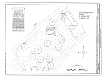
2. Learn views in the architecture drawing
As you can guess by its definition, a floor plan is the most important construction drawing.
A sight from top presenting the arrangement of places in building similarly as a map, but viewing the planning at a specific stage of a building.
It is a horizontal fragment section through a building (usually at four feet / one meter and twenty centimeters over ground level), appearing walls, windows and door openings and other features at that level.
The plan view incorporates anything that visible under that level: the ground, stairs (but only up to the plan level), furnishings and sometimes furniture.

Substance on top of the sketch stage (e.g., beams overhead indicated as dashed lines.
Geometrically, plan view defined as an upright orthographic projection of an article on to a straight plane, with the horizontal plane cutting through the building.
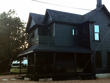
3. The elevation is the main part of drawings
It is time to talk about the elevation. An elevation is a sight of a building seen from one face, a plane illustration of a single façade. Thus it is the commonly used view to depict the outer facade of a building.
- Every elevation called in connection with the compass way it faces, e.g., looking toward the north you would be considering the southern elevation of the building.
- Buildings are rarely a plain rectangular form in design, so a usual elevation can display all the parts of the building that visible for starting a specific direction.
- Architects, also, employ the phrase elevation as a synonym for façade, so the north elevation is the north-facing wall of the building.
4. Cross section can cut the building
It turns to cross-sections in construction drawing. A cross segment, also clearly referred to as a section, represents a vertical plane reduce through the item. Identically as a ground plan is a horizontal segment considered from the pinnacle in abstract architectural drawing.
In the segment view, the whole lot cut by way of the segment plane proven as an ambitious line, often with a strong fill to expose objects that reduced through, and something visible past typically is visible in a thinner line.

We use sections to explain the connection among special levels of a building. In the Observatories drawing illustrated right here, the segment shows the dome which visible from the outdoors.
A second dome that can most effectively be visible within the building, and the way the distance between the 2 incorporates a massive astronomical telescope: relationships that might be tough to recognize from plans by myself.
A sectional elevation is a mixture of a passing phase, with elevations of other elements of the building visible beyond the chase aircraft.
Geometrically, a move phase is a horizontal orthographic projection of a building directly to a vertical plane, with the vertical aircraft slicing through the building
5. Details are necessary for sections
Let me talk about detailing of the construction drawing. Detail drawings show a small a part of the construction at a bigger scale, to expose how the component elements suit together.
We use them to show small surface info, for instance, decorative factors. Section drawings at huge scale are a popular manner of showing building production details.
Typically displaying complex junctions (such as ground to wall junction, window openings, eaves, and roof apex) that are not visible on an architectural drawing that consists of the total top of the constructing.

A complete set of construction information wishes to show plan details in addition to vertical section information.
One element produced in isolation: a set of info suggests the facts had to recognize the development in 3d. Usual scales for details are 1/10, 1/5 and full length.
In conventional creation, many details that few element drawings had been required to assemble a constructing.
For example, the construction of a sash window left to the chippie, who might completely recognize what become required, but specific decorative info of the facade drawn up in detail.
In the assessment, current buildings want to be fully special due to the proliferation of different merchandise, strategies and viable answers.
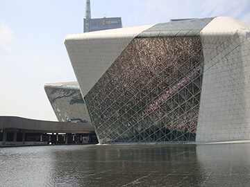
6. Abstract architecture drawing is still unpopular
Abstract architecture drawing addresses the process of elimination so that it will reach the crucial datum of things.
In a layout world, increasingly more dominated using organic and redundant forms, abstract architecture drawing is possibly to be one of the most unpopular ideas in the discipline of architectural concept.
Sketches are important in architecture drawing and abstract architectural drawing. But, how?
A sketch is a rapidly performed freehand drawing, a brief manner to record an increase in a concept, now not supposed as a finished work.

In structure, the completed work is highly priced and time-consuming, so it is far essential to solving the layout as completely as feasible before production paintings begin.
Complicated current homes involve a big team of various specialist disciplines, and conversation at the early layout stages is important to hold the layout shifting towards a coordinated outcome.
Architects (and other designers) start investigating a brand new layout with sketches and diagrams, to develop a tough layout that offers an adequate reaction to the specific design issues.
There are two primary factors to building design, the aesthetic and the practical. In the early stages of the design, architects use diagrams to develop, discover, and talk ideas and answers.
These are critical tools for wondering, problem-solving, and communication inside the layout disciplines. Diagrams used to clear up spatial relationships, but they also can represent forces and flows.
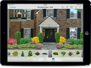
7. CAD application in construction drawing
After abstract architectural drawing, Construction drawing are important to note. Until the latter a part of the twentieth century, all architectural drawing manually produced.
If now not by way of the architects, then by means of educated (but less skilled) draughtsman (or drafters), who did no longer generate the design, but did make some of the much less essential choices.
This system has persevered with CAD druggeting: many design architects have very little knowledge of CAD software program, relying upon others to take their designs past the caricature level.
Draughtsman regularly focuses one kind of shape, consisting of residential or commercial, or in a type of creation: timber frame, bolstered concrete, prefabrication, and so on.

The conventional gear of the architect has been the drawing board or druggeting table, T-square and setsquares, protractor, compasses, pencil, and drawing pens of different sorts.
- Drawings made on vellum covered linen, and tracing paper.
- Lettering accomplished via hand, mechanically the usage of a stencil, or a mixture of the two.
- Ink strains are drawn with a ruling pen, an especially state-of-the-art tool much like a dip-in pen, but with adjustable line width, capable of producing a best-managed line width.
- Ink pens needed to dip into ink often.
Draughtsman labored standing up, maintaining the ink on a separate desk to avoid spilling ink at the drawing.
Conclusion
As you have seen in previous parts, there are different sections in architectural drawing. Construction drawing are prepared using Cad software in specific criteria and limitations.
These drawings are available in different scales including detailed information.
I have explained the architecture drawing including abstract architecture drawing and construction drawing details. Please share your own experience in architectural drawing.


Comments